
Results 1 to 5 of 5
-
March 13th, 2012, 07:49 PM #1
 Super Member


- Join Date
- Feb 2012
- Location
-
New Hope,
Pennsylvania
(Bucks County) - Posts
- 645
- Rep Power
- 3251262
 Crimson Trace Rail Master Review - Part 1: Unboxing and Installation
My Crimson Trace Rail Master was ordered from Amazon on Saturday with standard shipping. Amazingly, USPS delivered it today (Tuesday) lol. I've decided to do a 2- or perhaps 3-part text review with a couple of key photos. Afterwards I may use this as a script for a video review.
CMR-201 Part 1 - Unboxing and installation
Inside the shipping carton, the product itself is contained in a smart, black box ~ 5" x 3" x 2" high. The box contains:
1. A foam pouch containing the Laser unit,
2. A small ziploc bag containing 3 "inserts", 2 cleaning swabs, 2 allen wrenches. laser warning labels, and a battery,
3. Instructions on a single 10"x11" sheet of glossy paper folded up mini-pamphlet style.
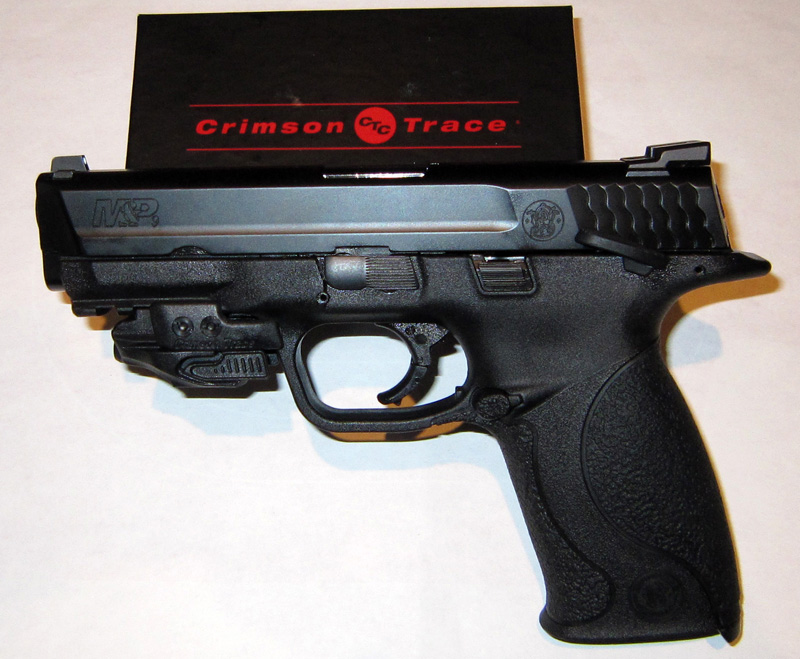
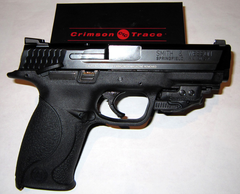
The Laser Unit itself consists of three pre-assembled pieces (see Crimson Trace CMR-201 for close-up views): the laser and switches, an "insert" that fits into a notch in the rail of your gun, and a pair of clamps that hold the laser and "insert" to the gun rail using 2 long screws. Three additional inserts of progressively longer lengths are also provided. Each insert will move the activation switches slightly further toward the trigger guard from the rail notch in which the laser is secured. The unit comes with the shortest insert installed.
I decided to begin installation of the unit with the shortest "insert" (#1) that was pre-installed.
After following the standard firearm safety practices on my M&P9, one loosens the two long screws opening the clamps. Then rest one clamp on top of the rail and align the tab on the "insert" with a rail notch. Then rotate the assembly so that the insert drops fully into that notch and the second clamp is above the rail. Tighten the screws a bit, slide the assembly forward back as much as the "insert" and rail notch allow, then tighten securely. The unit is installed.
I've never attached anything to a rail before, so it took me 2 whole minutes to figure that out.
As shown in this photo, using "insert" #1 left a 3/32" gap between the activation switches and the trigger guard. I decided to see how the activation switches worked before going any further.
Installing the battery comes next: remove battery from protective plastic/cardboard bubble, remove battery cover from Laser (it takes some force to do that, which is probably a good thing), and insert battery negative pole toward rail. Well, the battery doesn't drop in far enough - it must be pushed in to allow the cover to be re-installed. Pushing the battery in works; it stays down while you easily slide the battery case cover back on. Good
Now to activate the Laser. Tap the switch. Nothing. Tap again. Nothing. PUSH the switch - bingo. OK. you don't just tap this switch, at least not right out of the box lol. You must push it firmly. Now, let's see what the laser looks like on an 11"x17" target at 7 yards.


The instructions say the laser is factory sighted at 50', and that most people sight their laser for between 20' and 50' adding the following comment: "However, because of the offset between the laser sight and the bore, the actual change in point-of-impact at these distances is very small."
A quick comparison of my laser to the iron sights showed the laser's windage nearly dead on. However, the Laser was south of the 7-ring when the iron sights are where I believe the 10 to be
At this point I decided to reinstall the Laser to see how other "inserts" changed the position of the activation triggers. In the process I could also see if re-installation(s) changed sighting and/or corrected the elevation sighting error.
I tried all of the "inserts", and checked sighting after each installation. The good news? Insert #4 closed that 3/32" gap to the trigger guard very nicely. And I did not notice a change in where the laser hit the target vs the iron sights. IOW, any change that might have occurred was not large enough to be noticed without actually firing groups. The "bad" news? Elevation remains low.
[It was at this point that I noticed a table in the instructions showing that "inserts" #1 and $4 fit the S&W M&P9c, and "insert" #1 fit the M&P9. RTFM lol. #4 works better on the 9fs IMHO).
On to adjusting the laser sight . . .
IMO, the sight adjustment instructions are insufficient. Which screw controls elevation and windage is not shown. To be pickier, the only advice given is "A little adjustment goes a long way. Rarely is more than half a turn required to make your needed adjustments." While this is perhaps standard, there is no reason they couldn't add (eg,) a 1/4 turn in elevation will often yield approximately X" change at Y' ". To be ultra-picky, there is no mention that "clockwise" is judged as you look at the adjustment screw. And what do "up" and "down" mean in this context? While some may judge these criticisms ridiculous, it takes no more space than was actually used to create instructions that would improve customer success and satisfaction.
So, I judged the bottom screw to be "elevation". Using one of the two supplied allen wrenches, I decided to try a 1/4 counter-clockwise turn, guessing this should bring the laser "up".Let's see what happens: 7-ring . . . another 1/4 turn . . . border 8/9. A 135 degree turn. Bullseye, or close enough for handheld government work.
Overall, I'm actually very pleased with what I've found so far - don't let the instruction critique put you off, no one gets it right. As for the quality of the laser image at 7 yards, I'll leave that to you to judge. Due to mild cataracts, my description of the laser image isn't the same as my wife.s, nor would it match yours.
Well, that's all for now. On Friday I'll let you know what happened at the range.
-
March 13th, 2012, 09:38 PM #2
Grand Member

- Join Date
- Dec 2008
- Location
-
Scranton,
Pennsylvania
(Lackawanna County) - Posts
- 2,869
- Rep Power
- 21474854
Re: Crimson Trace Rail Master Review - Part 1: Unboxing and Installation
Nice writeup so far. It looks like it would be at home on a fiveseven.
When you get the sight dialed in, put a drop of clear nail polish in the screw holes so the little buggers don't creep!"...a REPUBLIC, if you can keep it."
-
March 13th, 2012, 10:15 PM #3
Grand Member
- Join Date
- May 2010
- Location
-
Butler,
Pennsylvania
(Butler County) - Age
- 73
- Posts
- 1,053
- Rep Power
- 16314
Re: Crimson Trace Rail Master Review - Part 1: Unboxing and Installation
Nice right up. Drop CT an email about the instructions. I have their grip mounted laser on my XD and their LCP laser. The instrustions for both locate adjustment screws and defines turn direction.
JMO CT is quality/reliable. I'd consider getting for for my XDM but it won't work with any of my holsters.
-
March 13th, 2012, 11:28 PM #4
Super Member
- Join Date
- Feb 2012
- Location
-
New Hope,
Pennsylvania
(Bucks County) - Posts
- 645
- Rep Power
- 3251262
Re: Crimson Trace Rail Master Review - Part 1: Unboxing and Installation
I did notice something else that prompts a question for you more experienced folks.
Neither "insert" fully fills the notch it fits into on the rail. The #4 insert I'm using now doesn't contact any point of the rail at all. So, the only thing holding the laser in position is the pressure of the two clamps themselves.
Is this normal for rail-attached accesories?
-
March 13th, 2012, 11:57 PM #5
Grand Member
- Join Date
- Jul 2010
- Location
-
610
- Posts
- 1,802
- Rep Power
- 42664
Re: Crimson Trace Rail Master Review - Part 1: Unboxing and Installation
From the small ammount of experience I have with rail mounted accessories, I'd say its perfectly normal and I'd almost prefer little to no contact of the "bolt" or whatever you'd like to call it contacting the rail. Potentialy boogering them up. That said. Originally Posted by Twoboxer

Great right up so far. IMO, CT took a page out of Armalaser's ( http://www.armalaser.com/content.cgi ) book, put their spin on it, and made it better. Before CT jumped in, there was nobody else in the iddy-biddy laser game. Yeah, there was Lasermax but, their offerings were bigger.
CT is top tier. I'm sure you'll be pleased. Subscribed for part 2&3. Thank you so far.


 Reply With Quote

Similar Threads
-
Kel Tec PF9 Crimson Trace
By Concealed9mm in forum GeneralReplies: 3Last Post: August 28th, 2009, 09:43 PM -
Sig P226 Crimson Trace review (short)
By WhiteShadow in forum GeneralReplies: 2Last Post: August 17th, 2009, 12:43 PM -
WTS: SIG P220 Crimson Trace w/ Crimson Laser, NIB
By Oberfeld in forum GeneralReplies: 2Last Post: January 23rd, 2008, 03:41 PM

Bookmarks